Saturday, April 11, 2015

Starting to See a Tiny Bit of "Light at the End of the Tunnel"


Cabin (Cuddy) Carlins & Cleats


Here you can see the cabin carlins (roof supports across the top) and side cleats as the glue is curing.  Later the carlins will be trimmed flush with bulkhead 1 (at the bottom of the picture).  The view is from the bow end.
.
Outboard Cleats from Bulkhead 2 to Bow, Carlins
Here is another view from behind bulkhead 2, looking toward the bow.  You can also see cleats being glued in the front "anchor well" at the bow end.

New Upper Breasthook
I had to build a new breasthook because the one supplied in the kit was too narrow.  Things look pretty messy because I tried to make the original breasthook fit and when I finally decided to remove it the glue had already cured, so it ripped out some of the port cleat.  I had to fill in the gap with thickened epoxy (thickened with wood flour).

Upper Breasthook
Here's the upper breasthook after sanding.  I got a bit overzealous trying to smooth out the filled area and sanded through the top layer of plywood.  No worries, though, the new breasthook is made of two pieces of plywood laminated together and is a bit thicker than the original. 

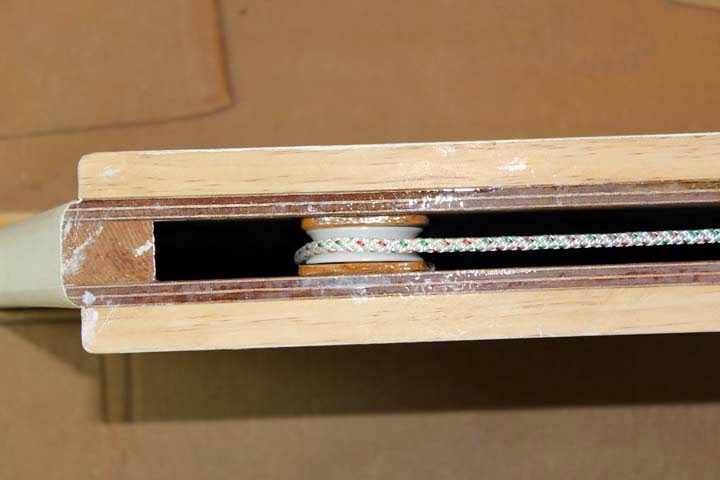
Starboard Outboard Stringer
This shows the outboard stringer being glued.  The inboard stringer and lower stringer are already in place.  Screws holding the lower stringer for gluing will be removed later.  The seatback will be glued to the stringers and frames after a vertical stringer has been added at the front end and some other work is done.  The top stringers will support the top of the seat, which in nautical terms is referred to as the "deck"in this case. 

 You can also see the stub end of the electrical conduit coming from the front storage and battery compartment to the stern.  There is another on the port side.  I decided to cut a section of the conduit out in the lowest bilge.  That way any water that finds its way into the conduit will drain into the bilge and can be easily removed.

Floatation foam will go in the forward seatback sections.  I did not cut rigid foam to put in there because there would be plenty of voids.  If water ever gets in I probably won't know anything about it unless I hear it sloshing around, and there would be no way to get it out short of drilling holes.  So I am planning to fill the areas with expanding foam, that if done properly will completely fill the seatbacks, leaving no place for water infiltration.

Port Seatback Curing
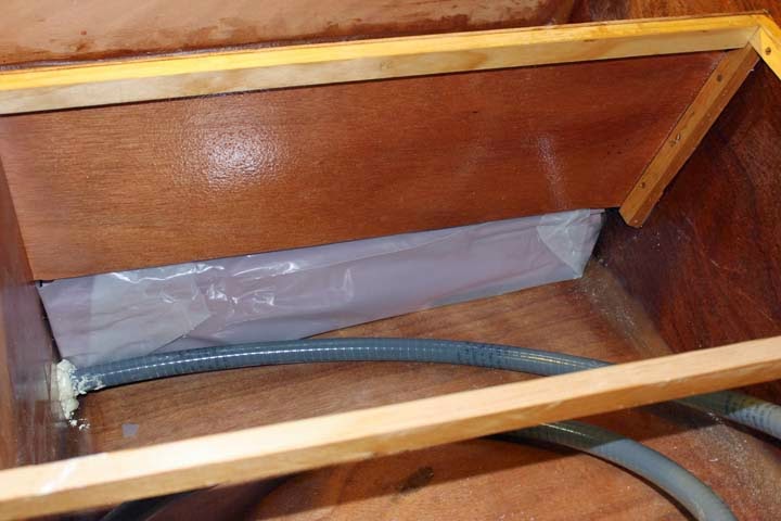
Starboard Setback Curing
Seatbacks are glued in and shown curing here.  The lower stringer and frame attachments could not be clamped, so instead I secured them with brads using a nail gun.  The tiny brads will remain, forever entombed in epoxy.  You can also see blue conduit in the rear storage "locker" on the port side. That will be used to route the VHF antenna cable to the antenna which will be mounted at the stern.  I also ran identical conduit on the starboard side to accommodate any electrical needs I have not anticipated.

With the seatbacks in place, my next steps include building the dorade boxes,* cabin deck, and companionway hatch, followed by installation of the seatback "decks" and fiberglassing the cockpit interior.  Then it's on to flipping the boat over and finishing the hull!

*A dorade box is a box with a horn vent mounted on top and a vent opening into the cabin.  The cabin vent is placed an inch or so above the bottom of the dorade box, so that any water that gets in via the horn vent will flow out through a hole in the hull before it gets high enough to reach the cabin vent.  This will become much clearer with pictures, I'm sure.

Thursday, March 19, 2015

Moving Right Along

The forward compartment is also filled with floatation foam.  Shown here, a tunnel has been created in the middle of the compartment.
This is to allow access to the bow-eye, which cannot be installed until the boat is nearly finished.  Access is provided through the inspection plate seen in the storage compartment.  From this angle it does not appear to be aligned with the tunnel, although it of course is.  I cut the first two foam pieces to fit very snugly, but it required quite a bit of twisting and maneuvering to get them in place in the bow, especially with the wooden breasthook in the way.  You can see the breasthook in the upper left.  Because of that and the bow's shape, the remainder of the foam is made up of variously-sized rectangles and odd scraps, which allowed me to fill it completely, leaving very few empty spaces.  After the bow-eye is installed, long rectangular pieces that will fit through the inspection hole will be added in order to fill the bow compartment with foam as thoroughly as possible.

Here is a shot of the tunnel from straight overhead.

Bulkhead 2 Doublers


Checking through the builders' forum I found that a few people had problems with the mast pulling bulkhead 2 away from the cabin roof slightly under high wind load.  This could only happen if the shrouds were loose, but I suppose things like that can happen.  The recommended fix is to install doublers to shore up the bulkhead and provide more gluing area to the roof (and to keep the shrouds tight).  I found some scrap pieces of plywood that I think will do the job very well.  They have just been glued here and are being held in place with temporary screws.

Next on the list is to install the forward deck over the bow compartment.  The underside of the deck received three coats of epoxy to strengthen it and prevent water infiltration.

Forward Deck Underside
Here the deck has been installed over the bow compartment and is held in place with countersunk brads during gluing.  The brads will not be removed.

Forward Deck Installed
Next come the seat-back braces back in the cockpit.
Interestingly enough, the braces are held in place with hot-melt glue (temporarily stitched with wire.  The braces will also be filleted, but I found the hot-melt glue provides a very strong bond--I used acrylic glue.  I tested the glue on some scraps and when I pulled them apart, wood came off with the glue.

The next step is to stitch in the rear cabin wall, shown here.

I have a temporary prop holding the wall at the approximate correct angle, but it will be easy to set it to the exact angle when the topsides panels are installed.

  Here is a shot of the topsides panels stitched nearly in place.  Later I will gradually tighten the stitches as I work to get the panels as perfectly placed as possible. 


And here you can see the view from the bow, which begins to show more of what the finished boat will look like.  There is still a roof and companionway to install over the cabin, seatbacks, and quite a few more odds and ends to accomplish before I am ready to flip the boat over and work on the hull.  But, it is really starting to come along.

Sunday, March 15, 2015

Centerboard Pendant Sheave, Cockpit, & Bow-eye

Sheave Installation
 
The manual shows installing this sheave (like a pulley) later on, but I felt it would be easier to do it now.  The sheave is nylon, and I have added wood shims to each side so the centerboard pendant can't slip off the side of the sheave.  
A bit of line has been threaded through the hole at the back of the trunk and over the sheave, down to the outside of the boat.  This line will be used to pull the centerboard pendant into place later on.
 
Here's the threading line through the hole and a grommet.  The grommet will be pounded into the hole later after some epoxy work is done.  When the grommet is installed and the pendant threaded into place, the pendant will be used to raise and lower the centerboard.
 
Here's a shot of the sheave bolt.  The notch for the bolt (and nut on the other side) was my idea.  Otherwise I would not have been able to tighten the nut.  I also used a lock nut instead of the acorn nut called for.  Not as pretty, but it will never loosen on its own.

 Cockpit Footwell and Seat Installation

Here is a shot of the just-installed cockpit footwell with fillets,
and another shot of the outside of the footwell.

This shows the cockpit seats glued in place.  The black spots are the heads of drywall screws which are only there to hold the seats down during gluing.  They will be removed and the holes filled after the glue cures.

Under the footwell I have added several layers of sheet foam for floatation if the boat is swamped--one of many areas of floatation foam to be added.  Although the foam is "closed cell," if it is in water for a very long time it can begin soaking it up, so I have put sheet plastic around the foam.  There was no point in trying to put the plastic all around the foam and seal it up because then I would not have been able to stuff it in there.  Instead the plastic goes up to about the level of the bottom of the footwell.  The corners are secured with storage tape.  As long as I don't get more than a few inches of water in there it should be fine.  If the compartment is ever completely flooded then I'll have to reach in and pull the plastic out.  From then on if it gets wet I will have to pull the plug and let it slowly dry out. 

Bow-eye Backer
  
Although the manual calls for installation of the bow-eye much later (after the boat is mostly complete), I felt that would be almost impossible to do--at least for me.  The bow eye is installed in the stem end at the front of the bow compartment, which is sealed up except for a small inspection port, and you have to crawl partway into the storage compartment to get to the inspection port.  Also the eye's bolts are attached to a small metal plate that is pulled against the stem end.  Since this eye is used to pull the boat onto the trailer and help hold it there during travel, I felt that it needed more backup.  To that end, I drilled two oversize holes for the eye's bolts and filled them with thickened epoxy.  Then I embedded a shaped stick of wood in more thickened epoxy over the holes.  As you can see the wood is only held in place with tape during the cure.  I did this so there will be a layer of thickened epoxy between the wood and the hull.  The wood is about five inches long and 1 1/2" wide, which should spread the load quite a bit.  After the epoxy cures, I'll drill the proper size holes through the oversized holes in the hull and on through the wood backer.  Then I'll oversize the holes in the wood, fill them with epoxy, and drill properly sized holes when the epoxy cures.  Whew!  I can't permanently install the bow-eye until the outside of the hull is finished, but at least the holes and backer will already be there.  I'll just have to cut away the fiberglass on the outside.  After the hull is painted I can install the bow-eye.  Double-whew!

Tuesday, March 10, 2015

More Work on Cockpit Seats and Footwell

The cockpit seats are a very close fit, but not all hulls curve exactly the same so some trimming had to be done.  I didn't get pictures of marking the areas to be trimmed on the sides, etc., but here is a shot of the seats sitting in place for marking:
Over the centerboard trunk, the seats overlap slightly, so I also trimmed those to fit exactly (more or less) in the middle of the trunk:
You can also see an "oops" that had to be filled in.  Somehow two pieces of plywood got stuck together with epoxy and this is what happened when I pulled them apart.  I filled the hole with epoxy-based fairing compound.

BUILDERS TAKE NOTE: The manual calls for sanding and painting the underside of the cockpit seat and footwell after they are glued in place.  That looks like an extremely hard and messy job since the seat is less than two feet above the cuddy floor and the bottom of the footwell only about 8 inches above the floor.  I was about to decide not to paint that area at all, but then it occurred to me to do the work before installation, as follows:

First the underside of the cockpit seats and footwell are sanded, being sure to sand very well the areas that will be glued (this was not mentioned in the manual).
Here are the seats and footwell sides sanded--I forgot the footwell floor until after this shot was taken.  All the areas that will be glued to cleats, bulkheads, and the centerboard trunk are masked.  I am not going to paint the area of the seats in the transom compartment, so no masking back there.  (You can see a few spots where I sanded through to bare wood, but that is inside the cuddy and fairly high up, so I'm going to leave as-is.  The oil-based primer should protect those areas in the off-chance that water ever gets up there.)
Here the undersides of the cockpit seats and footwell have got their primer coat.  I'll be adding the first finish coat later this evening.  After the cockpit parts are installed, all I'll have to do inside the cuddy is the cutting in.  A bit of a pain, but the sanding is already done, and much easier than painting the whole thing.

I plan to follow the same method on the front deck.  In the meantime I am crossing my fingers in hopes that John Harris did not have some darn good reason for waiting to sand and paint these areas after installation.  I've racked my brains and cannot think of any reason not to do it this way. 


Saturday, February 21, 2015

Cuddy and Transom Compartment

Things are starting to come together more now and I think you'll be able to get a much better idea of how the boat will look.  The floorboards are permanently in place (I hope).
Floorboards

I have made several changes to the cuddy floor and to bulkhead 8 (BH8), just aft of the floor, as discussed in previous posts.  

Aft end of Cuddy Floor
The floor was originally planned to reach all the way to BH8.  Instead, I added another floor joist that enabled me to install all the boards at the convenient and less expensive 8-foot length.  At some point I will be building a small lift-out or hinged panel from the new floor joist to BH8.  This can be done at any time, even after the boat is finished and launched, but as you will soon see it would be much easier to do it before the cockpit seat and floor are installed.  The opening is to allow access to wiring and the BH8 drain plug. 

On each side I have installed plastic conduit leading from the front storage/battery compartment to the two aft-most corners of the boat.  Heavy (6AWG) DC wiring and things like VHF antenna coax will be run through the conduits.  The holes in BH8 for the conduit (not part of the original plans) have been sealed with marine-grade sealant foam.  Looks messy, but will do the job (those of you who have used "Great Stuff" know how hard it is to be neat with this kind of foam).  The foam seals can be cleaned up with a knife and sandpaper, but they are in an awkward position and I don't want to take a chance on cutting into the epoxy.  After the cockpit is in place, they can only be seen by crawling back into a very small space.  I hate to leave them like this, but it is better than taking a chance on compromising the epoxy seal.
Inside Transom Compartment
 Inside the transom compartment you can see the conduits and their seals.  I have painted the bilge area with more of the epoxy-based bilge paint.  The instructions call for the entire compartment interior to be painted, but for the life of me I can't think of a good reason to do that, so for now at least I'm going to leave it as is.  Everything is covered with several coats of epoxy.  The epoxy can be damaged by sunlight, will be protected from the sun.  Sunlight can reach small areas of the compartment floor when the "lazarette" hatches are open, so I may decide to paint those areas.
Modifications to Floor and BH8
Two small (14 AWG) wires have been run alongside the conduits from front to back in case I later find a need for electricity in the rear of the cuddy.  The new standard for DC wiring is red for positive and yellow for negative.  This is to avoid confusion with AC code, where black is the "hot" wire. You can also see strings I ran alongside the conduits.  These will enable me to easily pull more wire if I ever need to.

In the bottom-center of BH8 I have installed a small drain plug.  The transom compartment is supposed to stay relatively water-tight and help keep the boat afloat if it is ever flooded.  (There will also be a lot of floatation foam in that compartment and several other areas of the boat.)  There will be two "lazarette" hatches to allow access to storage inside the transom compartment.  These hatches have been known to leak, so any water that gets in must be removed.  My modification was to install the drain plug so I can drain water from the transom compartment into the cuddy bilges where it will be much easier to pump out.  I just have to always remember to replace the plug before sailing.  There is another plug that goes in the forward-most bulkhead for the same purpose.  The hull hardware kit included two of these plugs and I read somewhere that the BH8 plug was part of the original design, but later discarded.

Cockpit Footwell Dry Fit

This seems like a good time to show you how the cockpit and its footwell will affect the cuddy space.  The dry-fitting of the footwell comes a little later in the instructions, but I'm doing it now for illustration.
Footwell Dry Fit

As you can see in the above photo, the footwell intrudes into the cuddy space.  The cockpit seat will intrude all the way to the front end of the centerboard trunk, some of which appears in the photo.  So from the CB trunk back, the cuddy roof is only about 1'4" high.  (Under the footwell it is only a little over 6" high.)  But the cuddy floor is 4'3" long from the front storage compartment to the CB trunk, and in that area the roof is over three feet high.  The idea is that the forward area of the cuddy is for sitting around in, and the rear area is for stretching your legs out when sleeping.  Two basketball players could fit in there comfortably (as long as they are careful not to bark their shins on bulkhead 7 while stretching out).  The cuddy is obviously pretty tight, but it is the roomiest I was able to find in any boat this size.

Footwell and Transom Compartment
This shot shows the footwell and transom compartment.  The two conduits have not been cut to length as yet, but they will come through holes I will cut in the cockpit seats near the aft corners.  (Those holes will also have to be sealed as in BH8.)  It is possible that water will eventually find its way inside the conduits, even though I plan to bend them downwards at the ends.  So I will need to find some way to temporarily plug them.  My Lake Michigan sailing friend, Orval Quamme, suggested plumber's putty, which I think is a great idea.  It will form a good seal, but can be easily removed when necessary.  (Orv is actually Jan's friend from High School in Madison, WI, but I have met him and we correspond quite a bit about boating.) 

Thursday, February 19, 2015

Painting Interior


Looking Forward--Primer Coat
Finished painting the interior of the cuddy and the forward storage compartment.  Here you can see a forward-looking view of the interior after application of the oil-based primer.  I did not paint above the level of the cockpit-seat cleats so as not to interfere with the glue and fillets that will be applied to the topsides panels later.  In this shot you can also see an unpainted section just behind the centerboard trunk.  The front ends of the cockpit footwell floor and sides will be attached there, so that unpainted section will actually be part of the outside of the boat.  You can also see two items I used to great advantage, a combination mixing/pouring lid on the paint can and a roller tray with lid.

Here is a closer shot:

Roller Tray With Lid and Mix/Pour Paint-Can Lid

These two items saved me a lot of time and quite a bit of paint.  I was able to simply snap the lid on the roller tray with the roller in it and re-use it the next day or even after two or three days.  That saved a lot of clean-up time and loss of paint--you can't pour every bit of it back into the can.  The mixing/pouring lid has a crank handle that rotates mixing panels inside the can and a trigger that opens the pouring spout.  This is again a big time-saver and saves some paint.  The mixing paddles do an excellent job of mixing the paint.  I got the roller tray with cover at Lowe's and the lid from Rockler Woodworking.

Looking Aft--Primer Coat
 Here's another shot, looking toward the stern, of the primer coat .  I did not paint the stern compartment yet.  Once the cuddy is finished I plan to install some of the floorboards to give me a nice platform to work from while painting the stern compartment.


Final Finish Coat--Cuddy and Storage Compartment
 Here are some shots after the second finish coat and installation of some of the floorboards.  The remaining boards have not had their finish applied, so I'll be installing them later.  I used a high-quality interior/exterior latex paint for the finish coats over an oil-based primer.  The Skerry is painted with Hatteras White Interlux Topsides paint and I like the color very much so I'll be using it for the white parts on the outside of the PocketShip's hull.  I took a sample of the Hatteras White to the paint store and we found a color for the interior paint that is a very close match.
Looking Aft--Final Finish Coat
 As I said earlier, the floorboards will give me a good platform for painting the stern compartment.  There was also touching up to do under the rear cleats and here and there in the storage compartment, so the floorboards gave me a very comfortable platform to work from on those jobs.
Wider Looking Forward--Final Coat

Saturday, February 7, 2015

Painting the Bilges


 At first I was thinking of not painting under the floorboards at all to save time, but eventually thought better of it.  Here you can see I am painting the bilge areas a light grey.  I am using an epoxy-based paint specially formulated for painting bilges.  All the grey bilge paint will be hidden under the floorboards.  Above the floorboards the walls of the cabin will be painted an off-white very similar in color to the Hatteras White I painted the Skerry, but I'll actually be using house paint.


Here are a couple shots of the bilges after painting the second coat.  I will probably add one more coat, then on to the cabin walls.